
I’m working on a new CM600 DRSSTC project, so in order to stir up some funding, I’ve finally decided to sell off some PCBs I made for my smaller TO247 IGBT coil last year. They are now available on eBay here.
Here’s an example of a DRSSTC I built with this board (but you can use this PCB for basically any purpose):

And here’s a very simple high voltage SMPS with the H-bridge board driving a homemade ferrite transformer. The driver is a TL494 and some gate drive chips deadbugged onto some blank copper clad board in an afternoon:
The boards are a derivative of the general purpose H-bridge design that I posted about in 2013, which I’ve had many requests to sell over the years. There are a few notable improvements that I’ll document here along with the rest of the design.
Key Features:
- H-Bridge with four spots for TO247 IGBTs or MOSFETs
- Gate protection network on each gate
- 0805 and 2010 dual package landing pattern for gate resistors
- 1.5KExxx series TVS across each TO247 device
- CDE940 series snubber capacitor
- Mounting space for two 1″-diameter GDTs
- SMA connectors for GDT drive signals
- Voltage doubler input with two TO220 diodes with heatsinks, two 10.16mm grid, 35mm diameter bus capacitors, and bleeder resistors
- 5mm x 20mm fuseholder
- 10AWG holes for external DC bus input
- 4oz copper on both sides with low inductance laminated bus structure
Digikey Bill of Materials (Excel file hosted in Dropbox)
Schematic:
Layout:
Top side scan: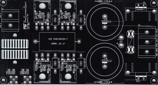
Bottom side scan:
CAD files are available upon request. Please send in any feedback you have so I can improve future versions of this board.
Currently, there is one known issue with the board; the labels on the mains input connector are wrong. They read “GND (GRN), NTRL (WHT), HOT (BLK)”, but they should read “GND (GRN), NTRL (BLK), HOT (WHT)”. Basically, the ground, neutral, and hot connections are labeled correctly, but their standard wire colors are not. Neutral is black and hot is white, not the other way around.

does the switching frequency of the H-Bridge is equal to the frequency of LC network in the tesla coil
Yes, and this is accomplished using a self-tuning feedback controller such as Steve Ward’s Universal DRSSTC Driver (try searching the archives on 4hv.org for more information and documentation).
Can the cad files be available to me ? I am second year engineering student and required the board for an urgent project on wireless battery charger system. This bridge design seems to be very suitable for our purpose. Please let me know if possible
It’s all on github: https://github.com/dkramnik/Tesla-Coils/tree/master/general_purpose_hbridge_rev2
Your Silkscreen is correct.
Hot is Black
Neutral is White
Ground is Green
Hi Justin,
Thanks for your response to my comment. Are there any assembled driver boards you can suggest that will make this h bridge output a square wave in 80-130 kHz frequency? I’ve been searching the internet but no luck
http://www.loneoceans.com/labs/sales/ud27/
Gao Guangyan sells assembled boards.
Hi!
I bought one of these pcb’s for a wireless inductive charger project. It has not arrived yet but I need a 100 kHz 110 V square wave to come out of the h-bridge. Would the standard list of components you have posted here work for that purpose? If not can you please give me some pointers as to what components to get?
Yes, this board can be used for that. You will need to design and build your own driver to generate the gate drive waveforms required for your application.
Thank you!
Would a 555 timer IC be a good choice to drive the transistors and how can I integrate that into the board because I’m looking at the schematics and the PCB layout and I don’t see a place for a gate driver IC but maybe since I’m a complete newbie I’m missing something. I’m an ME student doing this as a senior project and the deadline is fast approaching so I’d greatly appreciate any help.
The GDT1 on steve wards driver board carries the inverted signal which connects to one of the GDTs on the h-bridge and GDT2 from the driver board carries the non-inverted signal which connects to the other GDT on the h-bridge. Is my logic correct here?
Both outputs of the UD are phased the same iirc; you need to flip the primary phasing of one of the GDTs. You can always check the phasing of the signals with an oscilloscope and reverse GDT windings until you get it right. Make sure to use a current limited bench supply for testing in case you get it wrong.
You will need a separate board that generates the gate drive waveforms. This board has solder pads and SMA connectors for feeding the drive signals in. Remember that you will need to buffer your waveform with gate driver ICs and generate a symmetric differential waveform, otherwise the GDT cores will saturate.
Would Steve Ward’s Universal DRSSTC Driver do the job? Due to my limited electrical engineering knowledge I’m looking for whatever I can get “off the shelf”
Yes, you can just feed your input signal into the feedback CT input, short the OCD CT input so that noise doesn’t trip the current limit, and pull the interrupter input high.
Yes it would work fine but it’s a bit expensive if you don’t really need all of the other functionality, however it is a very robust method of driving the bridge and you can get assembled boards if you don’t like SMD soldering.
Sorry for hounding you again. I’ve tried to buy Steve Ward’s self tuning feedback controller board but I think they’re out of stock because they did not reply. Are there any other self-tuning controller boards out there that I could use to drive this h-bridge. Please help!
When you say pull the interrupter input high do you mean that I don’t need to use an interrupter along with the driver board and just connect the driver board interrupter input pin to a 5 V rail?
Yes, and you don’t need to install any fiber optic receivers.
I’m confused about the 5.6 ohm resistors near each IGBT. For example, R2 and R3 seem to refer to the same pad. The schematic also shows two 5.6 ohm resistors at this same location. Are we supposed to stack two 5.6 ohm resistors on top of each other at these locations? Thanks in advance.
It’s a dual footprint — you can use whichever size resistor you find more convenient for your needs. You cannot install both sizes of resistors simultaneously.
In case it helps anyone out, this is the heatsink I bought for mine:
http://www.ebay.com/itm/251941535498?_trksid=p2060353.m2749.l2649&ssPageName=STRK%3AMEBIDX%3AIT