Introduction
About a year and a half after the events of SGTC I, I finally got the chance to build a proper spark gap Tesla coil when I managed to grab a 9kV 30mA non-gfi neon sign transformer for only $30 on eBay. Normally, non-gfi NSTs go for many times this price, which had traditionally prohibited me from making larger spark gap Tesla Coils.
Here’s a picture:
The goals of this project were to achieve stable, 1 foot long air discharges and to learn more about SGTC construction.
As of April 16, 2011, this project is still under construction, although a working prototype has been built.
Design
While the difficulties in VTTC and SSTC construction lie in getting the oscillator to run properly and in cooling the tubes/transistors, the hardships involved in SGTC construction mainly revolve around physical assembly of the device. The schematic is quite simple and usually requires little or no debugging.
The component values are:
T: 9kV 30mA NST (270W)
C: 10nF LTR (Larger Than Resonant) metalized polypropylene MMC
Lp: about a dozen turns of thick wire in a flat spiral configuration, tapped every quarter turn
Ls: 18″ winding of 23AWG on a 3.5″ PVC pipe
Topload: 8″ diameter volleyball wrapped in Al foil (will be replaced with a 10″ toroid as soon as soon as this becomes an economically viable alternative)
Construction
February 14, 2011 (Valentine’s Day!)
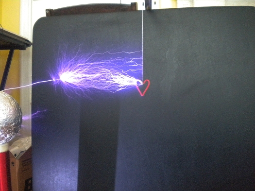
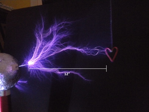
I took some photographs of the coil in action today. First light was achieved with a 6″ spherical toroid, a styrofoam ball warpped in Al foil, and a 14″ winding of 28AWG wire on a 2.5″ PVC pipe. Sparks are about a foot long, which corresponds to approximately 250kV of potential difference!
Here is a video of first light:
Later, I switched over to the 3.5″ secondary coil and 8″ spherical topload. As s result, spark length increased by a few inches.
Here is a video of the coil operating with various secondary coil/topload combinations:
And some pictures:
April 14, 2011
Finally, I had some free time to experiment with the Tesla coil and the weather was warm enough to set it up outside after dark. After tuning around for about half an hour, I found that:
1. The sparks were highly unstable, something I attribute to poor quenching in the single static spark gap and to the lack of a proper RF ground. Because this is a relatively small Tesla coil, I have been using mains ground instead; this is bad practice and will be discontinued. In my next series of tests, I will replace the single static gap with an air-quenched RQ style gap and use a metal pole hammered into the earth for RF ground.
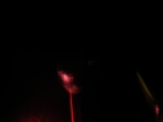
2. The long alligator clip wires that held everything together experienced severe heating to the point where plastic insulation began to melt and one connection even burned through. While I was taking pictures of spark discharges, I managed to capture the moment when the burn through occurred. The orange-red light is from the burning wire, luckily, no components other than the wire were damaged:
Once I build the new spark gap, I will assemble a box to house the coil and make short, thick connections in order to reduce leakage inductance and resistive heat losses. Hopefully, this will further improve the spark length.
May 23, 2011
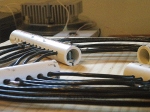
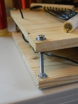
Because my new DRSSTC isn’t working and I only have two more days until my physics final project is due, I decided that it was time to revisit this coil by putting it on a permanent base and replacing the alligator clip connections with 10 gauge wire. As a result, the output was stabilized and I no longer have any problems with the coil failing to fire at its maximum potential. Instead of using an RQ style gap, I decided to use an ordinary single gap because it was easier to construct. However, instead of using two nails or bolts, I used one adjustable bolt and one large 1.5″ diameter washer that can be rotated using a screwdriver so that it will not be necessary to sand off any corrosion during my demonstration. Here are some pictures:
I also tried using a smooth Van de Graaff discharge terminal to eliminate losses due to coronal discharge, but I decided that it wasn’t worth the extra size. The discharge terminal is probably too large for this coil, so even though it suppresses coronal discharges, the spark length does not increase and the coil fails to break out on its own unless I use the smaller secondary, in which case it just arcs down toward the primary coil.
Here are some photos I took during construction:
Primary capacitor construction (trimming excess plexiglass after mounting the MMCs):
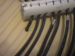
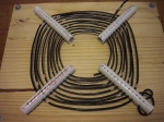
Primary coil and supports:
Unfortunately, I don’t yet have the ability to run a test with a proper RF ground, so I have been using my apartment’s mains ground so far. After I move in the next week or so, I plan on installing a grounding rod in my backyard and running a test.
July 11, 2011
I haven’t had the chance to run the coil with a proper ground yet, the best I was able to do was a small steel rod hammered about a foot into the ground. However, I posted a step-by-step guide to building this coil on instructables: http://www.instructables.com/id/How-To-Build-A-Spark-Gap-Tesla-Coil-SGTC/. It was featured on the instructables homepage, yay!
I also entered it into some instructables contests:
Conclusion
Although this project is only in the prototype stage, the results already exceed my stated goal of 1 foot long sparks.









hey i am doing this for a science fair project and i was thinking. i was unable to find a 23 gauge wire. i also wasn’t able to find a 10 gauge wire specificly what you mentioned. am i able to exchange the 23 for a 22 and the 10 to a 12?? and what would i do to the design so that it would change the output? please reply
oh also this info was from your page on Instructables
Changing the wire size of the secondary coil would require you to calculate your resonant frequency and tune the coil differently. However, I would not recommend using anything thicker than 23 gauge wire, in fact, I no longer use anything below 28 gauge wire on my new coils.
As for the primary coil, I wouldn’t recommend replicating what I did, especially with thinner wire. Try winding your coil with quarter or eighth inch flexible copper tubing. This will save you a lot of trouble un-insulating stranded wire and it will give better results (lower R losses).
If you have any more questions, feel free to ask!
so all the materials came in and i assembled it. how exactly is the secondary connected to the primary? BTW i was able to find the 23 gauge and the 10 gauge.
See the schematic – the primary and secondary are not connected: the bottom of the secondary is grounded and the top is where the sparks form!
any idea where i can get the caps?
digikey has min 1000 order at $1.85
Try searching eBay for similar items. I’d recommend just buying some CDE942 series caps.
Quick search
Those caps are close to $200 for 100
I can’t find anywhere in 2 months of searchIng the caps you spec for anywhere near the thirty some dollars you said you paid
The wire at the stop of the secondary has to be connected into the top load right?
And should the wire taped at the side of the top load be connected to this secondary wire?
The top of the secondary is indeed electrically connected to the topload, and the aluminum foil provides a path to the breakout point.
Of course. I later realized it was a dumb question indeed. Anyways, about using a Neon sign transformer, the power supply in my country is a 220V , 50HZ AC. and i doubt a neon sign transformer will be available here. Any substitutes to power the tesla coil?
also, how are the primary capacitors connected to the spark gap?
well?