Introduction
This project was built for the Water Quality Science Olympiad event. The rules manual just said “build a salinometer”, so this is what I came up with. The obvious choice, of course, is a simple mechanical hydrometer with maybe +/-5% salinity accuracy in the best case. This electronic solution (hehe!) has a theoretical accuracy of +/-0.0014% salinity, but some serial dilution is required to bring the sample into its range.
Build time: ~1.5 weeks
Sidenote: Ever since this page started making it way around the ‘net, I’ve been accused of getting excessive “assistance” from parents/adults and of winning by overspending on the project. Neither of these claims are true. I know how to use Eagle and etch my own circuit boards because I learned how to for my DRSSTC project, I can design and understand opamp circuits because I read the corresponding sections in The Art of Electronics, and I spent no more than $60 on this project, and only this much because I insisted on buying the parts in-store and not online due to time constraints.
Thanks for reading, please don’t be hostile!
-Daniel
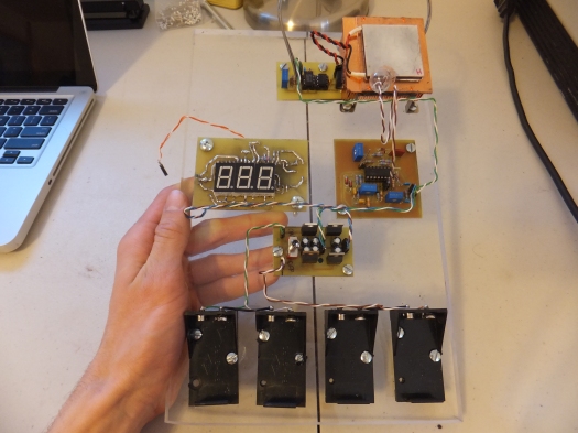
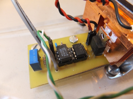
Completed View:
Design
The entire circuit consisted of several parts: an opamp-based salinity-measuring circuit, a linear positive/negative power supply, a digital voltmeter, and a peltier device temperature controller.
In order to save time debugging (inevitably) flawed bread or perfboarded circuits, I designed custom circuit boards in Eagle CAD and etched them at home with ferric chloride. I won’t post my .sch/.brd files as that would make it too easy to copy this project for Science Olympiad, but I will share schematic image files and board image files (if you already know how to reCAD them for etching in Eagle, chances are, you’re already beyond this guide :)).
1. Opamp Circuit:
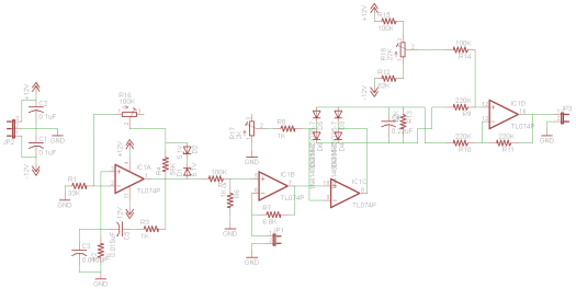
The first opamp is a Wien bridge oscillator, the second is a non-inverting amplifier with gain set by the AC impedance between the probe’s tips, the third is a full wave rectifier with a smoothing leaky peak detector, and the fourth is a differential amplifier that measures the potential between the DC poles of the rectifier. Due to time constraints, I copied the opamp circuit from http://www.octiva.net/projects/ppm/ in my project, failing to notice that it has several flaws: the non-inverting gain stage defaults to G = 1 with high impedance on the probe, so the range of the instrument is severely limited (this could easily be fixed by just making it an inverting stage – we don’t care if our AC signal is 180 degrees out of phase once we rectify it) and the full wave rectifier in the third opamp stage could be implemented in a better way that references it to ground, making the fourth stage and some of the biasing pots unnecessary.
Schematic:
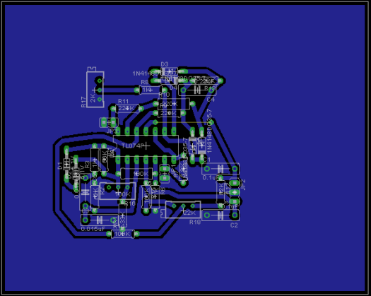
Board Layout:
(Edges are cropped out when printed, I just decided to keep Eagle’s default size)
2. Linear Regulator:
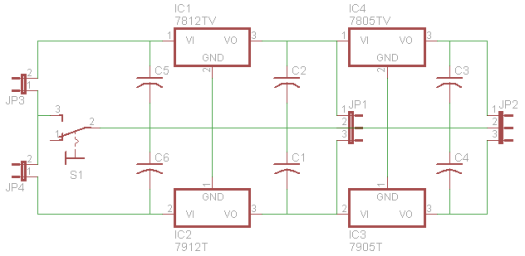
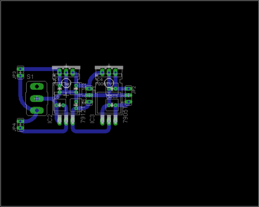
Nothing special here, just some 78xx/79xx ICs to regulate +/-18V from the four 9V batteries down to +/-12V and +/- 5V. It has more capacitors than it needs (they could be omitted in a low budget or low space situation), but I suppose it’s good practice. There is one error in this schematic: the switch should be SPDT and should connect the positive and negative inputs to the regulator, not the ground input. With the switch only connecting the ground input, there is some feedthrough in the ICs and power is wasted and weird voltages are supplied to the ICs- with the switch turned off! If anyone knows why this is occurring, I’d love to hear your explanation!
Schematic:
Board Layout:
(I couldn’t find any 79xx in a vertical package in Eagle, so I used the horizontal one instead – that’s why it looks like the negative regulators are battling it out across the circuit board with the filter caps)
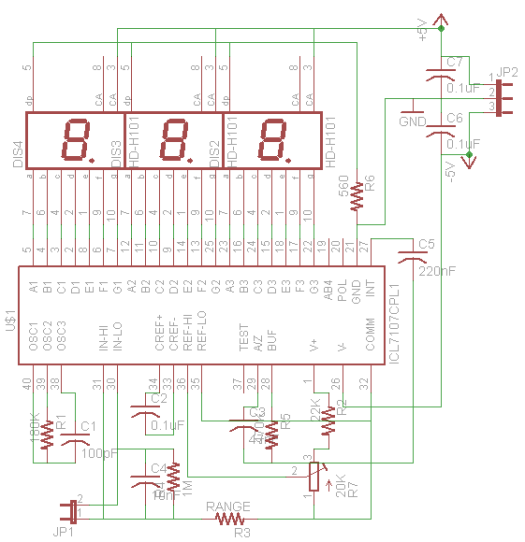
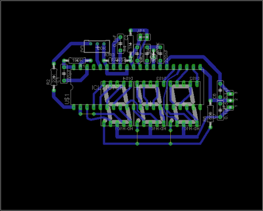
3. Digital Voltmeter:
A standard implementation of the ICL7107 with range 0 – 20V; the LED displays and IC are mounted on opposite sides, technically making this a 2-sided board (but not really, so don’t be intimidated)!
Schematic:
Board Layout:
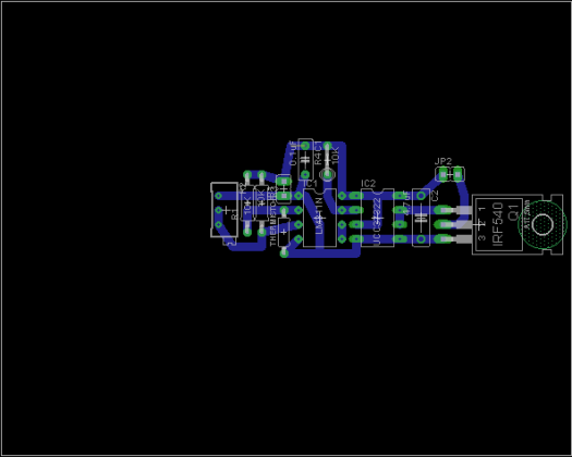
4. Temperature Controller:
This is a comparator circuit I designed to turn a high current heating element (with my favorite gate drive IC from my Tesla coils!) on when a thermistor senses that the temperature of the sample is below a certain set point and turn it off when it senses that the temperature is above that point. I didn’t add any hysteresis or PID control, with current reversing through the peltier rather than just shutting off, due to time constraints and because I didn’t feel it was absolutely necessary for the circuit to work. In fact, this entire part can be omitted completely if an ultra-precise measurement is not necessary because the conductivity of saline solution is not highly temperature-dependent.
Schematic:
Board Layout:
Construction
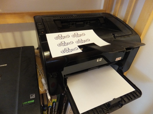
The circuit board layouts were printed on glossy paper with a laserjet printer (which type of glossy paper is my secret :P):
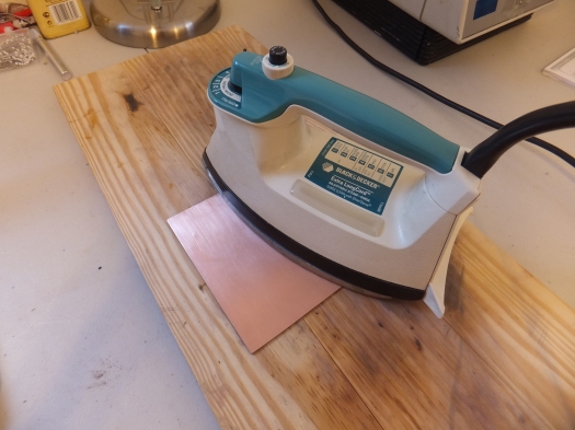
Next, they were ironed onto blank single-sided circuit board material:
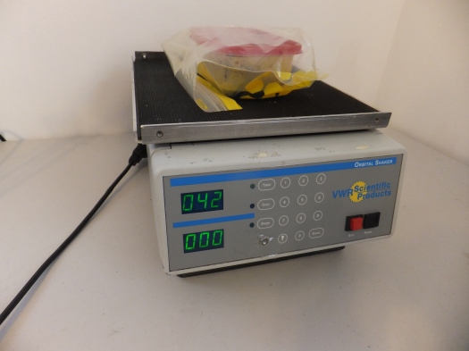
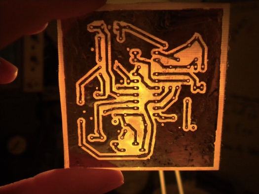
After that, I etched them in a bath of ferric chloride using a VWR Orbital Shaker; ask around local colleges and universities, they often have stuff to throw away (this particular one came from MIT):
Immediately after etching, the boards were tinned to prevent oxidation. It’s also good practice in power circuits (which these are not) that I inherited from Tesla coil building:
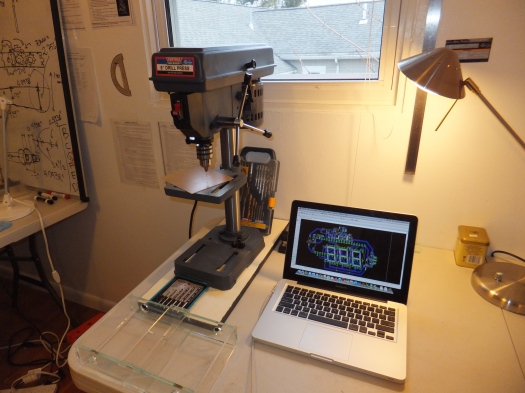
The boards were then drilled with an 0.035″ standard size PCB drill bit on my drill press (yay harborfreight!):
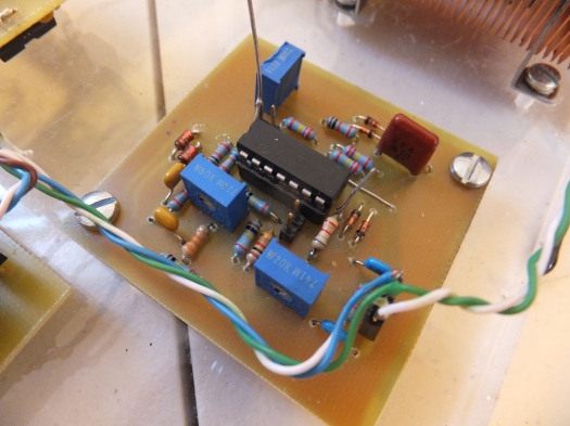
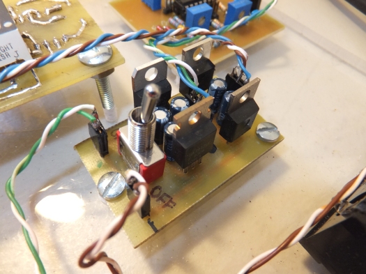
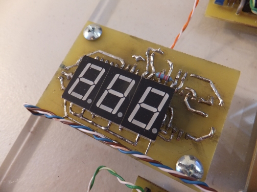
Finally, the boards were populated:
Opamp Circuit:
Linear Regulator:
Digital Voltmeter:
Temperature Controller:
The entire thing was assembled on a rectangular piece of acrylic and the circuit boards were secured with bolts via 8-32 tapped holes:
Testing
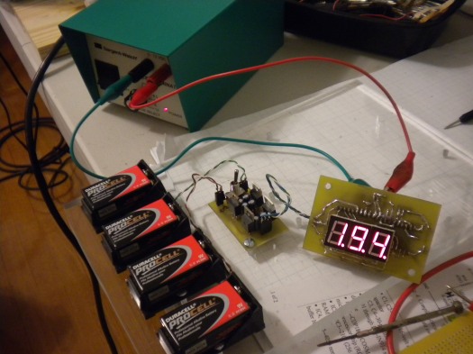
Confirming that the DVM works by measuring a power supply:
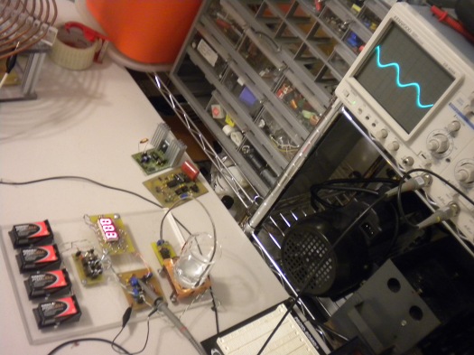
Tuning the amplitude of the Wien bridge oscillator (we want the lowest amplitude that will produce a clean sine wave in order to maximize the range):
Results
We won first place at regionals! (Although I’m told that may have been more a product of the team’s written score than salinometer score, as there was some error in the serial dilution; I didn’t go due to Harvard Extension finals) In any case, an improved version of this device will be making an appearance at the state competition in March.
Updates!
Water quality took second place at the MA state science olympiad on Saturday, March 18! (Again, the salinometer was only part of their score though)
I changed the gain-setting resistor in the non-inverting amplifier to 200 ohms to adjust the range of the instrument from 0 – a few percent salinity to 0 – roughly 20 percent salinity; practically, it can measure to about +/-0.25% salinity – still pretty good, and doesn’t require any serial dilution.
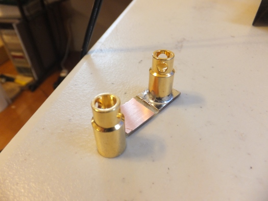
I also switched to gold-plated electrodes made from battery connectors for the probe ends to eliminate problems associated with corrosion:

A Salinometer built for the Science Olympiad - Hack a Day
A Salinometer built for the Science Olympiad » Geko Geek
For your mystery with the linear regulators: the 7812 can sink current to the 7912, and the 7805 can sink current to the 7905. So the current flows through two batteries, then through the 7812 and 7912, and finally back to the batteries.
A Salinometer built for the Science Olympiad | ro-Stire
What do you actually measure and how did you establish the accuracy?
By replacing the gain-setting resistor in the second opamp with the probe electrodes, the sine wave signal from the Wien bridge oscillator is scaled in a manner that depends on the AC impedance between the electrodes. Essentially, the thing measures the “AC resistance” of the saline solution, and we can calibrate the output voltage based on a few solutions of known concentration. Here’s an explanation from the EC/TDS/PPM Meter page:
“If EC/PPM is just measuring the Conductance (or resistance) then why not use a volt/ohm meter directly?? Because they pass DC current thru the probes and you cannot measure conductivity of salts with DC current because it will rip the molecules apart, and since the molecules are what conducts the electricity you get a constantly changing reading that is useless. Overcome this by using an AC signal. If the frequency is high enough (>1khz it seems) the molecules dont have time to move apart before they are pulled in the opposite direction. Sort of like how high DC current will throw a person off of it, where as AC forces them to hold on and get shocked to death or something.”
Calibrated the way it is, the minimum change in ppm that the salinometer can *theoretically* detect is 5ppm, which translates to an 0.0014% change in salinity (saturation occurs at around 359g. NaCl/L H2O)
DIY Digital Salinometer - Hacked Gadgets – DIY Tech Blog
DIY Digital Salinometer – DIY Tech Blog » Geko Geek
DIY Digital Salinometer - Free Plans, Hacks, Howto's and other DIY stuff - Free Plans Online
Hey Dude,
This is a great build. Loved reading your indepth build here. Really incredible stuff. Do you have an email I can grab you on? I have a few questions. Please drop me a line.
Thanks
Ryan
Hey there!
I’m daniel.kramnik (at) gmail.com – feel free to email me at any time.
-Daniel
You should be really proud of yourself, regardless of whether you got help or not. I’ve been looking through your projects and I’m jealous of how much you’ve finished! Keep up the good work, I’m SUPER impressed. If you’re doing projects like these now, I can’t imagine where you’ll be in ten years. Keep up the good work!
Wow, that’s pretty neat. I’m guess this was for the C Divison?
Greetings DANIEL
Digital Salinometer see the project is very impressive
I also make a research on Digital salinometer breathing, I applied to measure the salinity of the brackish water (ponds). but my experiments always fail. I have always been problematic in the output voltage.
Is this your Digital salinometer project can be used to read the salinity of the brackish water?
Will I be able to see more clearly that the probe you are using and have you connect with Opamp Circuits.
thank you
Awesome build! I was looking for a device like that to aid in raising brain shrimp as feed for (fresh water) aquarium fish. I am having too varying results and wonder if a better controlled salinity will help. They tolerate a lot of variation in salinity – 25-250 g/L – but I would love to find out what they actually prefer.
Thanks for the circuit and the theory behind it – I’ll try to build one myself.
Cheers!
Hi, great project; I am in water quality division b and I was looking up salinometer designs when I saw yours. It must of taken a long time to learn how it works and the circuits! Just one question, does the salinometer measure water conductivity or is there another mechanism?