
Obligatory picture at the beginning of my post so it doesn’t make my entire front page look like a wall of text:

A quick skim through my site will reveal that I haven’t been very diligent about posting new projects or filling in the many blank pages that are supposed to document my old ones. Sadly, I’ll probably be too busy with schoolwork until the summer to fix that, but in the meantime, I’ve decided to try something new; this page is going to have short weekly/monthly documentation of what I’m building, rather than some sort of weird chronological list of the projects I finally get around to posting about. In other words, this is finally going to be a real blog. Here it goes!
After about a year of playing around with all kinds of different H-bridge designs for my DRSSTC projects, I decided to put together a finalized general purpose H-bridge board that would work well for all kinds of small to medium-sized high voltage projects (read: those that don’t use bricks). Basically, any time I need an inverter for something like a Tesla coil or ferrite transformer, I want to be able to grab one of these boards, add a driver, and gogogo!
The first obvious design choice is mini brick (SOT-227), or TO-247? Seeing as mini bricks are about 5 to 10 times more expensive ($20 – $30 a pop, as opposed to $2 – $5 for the average TO-247), I’ve only ever used the latter in my projects. It’s been experimentally determined that it’s best to replace all the silicon on your bridge every time something fails (there’s an old 4hv thread on this out there somewhere), that means replacing an entire bridge on a TO-247-based coil after a device failure costs about as much as a single lower-end mini brick transistor. If that alone isn’t enough to convince you, here are some other reasons TO-247s are better at this scale:
1. Mini bricks have isolated metal backplates, while TO247s do not. At first glance, this might seem like a good thing because it means you can bolt all your mini bricks to the same heatsink without worrying about creating short circuits. The downside is that internally, the thermal contact between the die and the mounting plate is much poorer than what you get with a TO-247. A bridge of TO-247s with individual heatsinks is the ideal route to take, although silpads or the occasional surplus Beryllium Oxide heatsink insulators found on eBay will allow you to put the entire bridge on the same heatsink.
2. On average, mini bricks have much more gate charge and switch slower than TO-247 IGBTs. Beefy gate drivers with gate drive chips driving discrete FETs and phase lead networks (for feedback-tuned systems) can turn minibricks into a more viable option, but it’s nice not to have to go through all of that for a board that’s supposed to be easy to use.
3. Modern TO-247 IGBTs such as the Fairchild FGH60N60SMD can reliably handled peak currents as high as 300A (and probably more) in conventional DRSSTC use up to hundreds of kHz, which is good enough. While it’s possible to push some mini bricks up to insane currents as high as 1000A or more to get giant sparks out of little coils due to the mini bricks’ larger dies, it limits their average operating lifetimes down to 5 to 10 minutes due to rapid degradation of the silicon. The “old way” of making a DRSSTC was to push the primary current as high as possible and regularly replace the transistors (this practice was born back when mini bricks could be had as free samples by the box!), but that’s not generally considered to be a good idea anymore. If you need that much current, you can use a ferrite transformer to enforce current sharing between multiple bridges (see Steve Ward’s new phase-ramping QCW coil, it’s really clever!).
tl;dr: I used TO-247s.
Okay, now here’s the actual design of the board. Note that the IGBTs are meant to be mounted on the heatsink under the board:

Board layout
Key features:
– Laminated DC bus with a snubber very close to the transistors: The reason the positive and negative rails are right on top of each other is to keep the inductance between the bus capacitors and the transistors as low as possible. The stray capacitance of this arrangement lumps into the snubber capacitor, which also works to our benefit. The idea behind all of this is to minimize the bus inductance that gets excited during switching transients.
– Current transformer (compatible with standard Triad Magnetics CTs from Digikey) and coax cable connector on the board: this leaves one less unsecured or semi-secured thing flopping around the DRSSTC. The SMA cable connector is also much more reliable than a twisted pair of wires, which has actually been a failure point in one of my coils.
– GDT (gate drive transformer) mounting pads: yet another thing that would probably be better off not floating around between the driver board and the bridge!
– FUSE! A fast-acting fuse saves transistors (sometimes) and board trace explosions/things catching on fire (always).
– External connector pads: let you connect an external DC supply for testing, or a larger set of buscaps for a coil that runs long bursts (like a QCW).
Here’s the schematic (click to view – wordpress derped the preview):
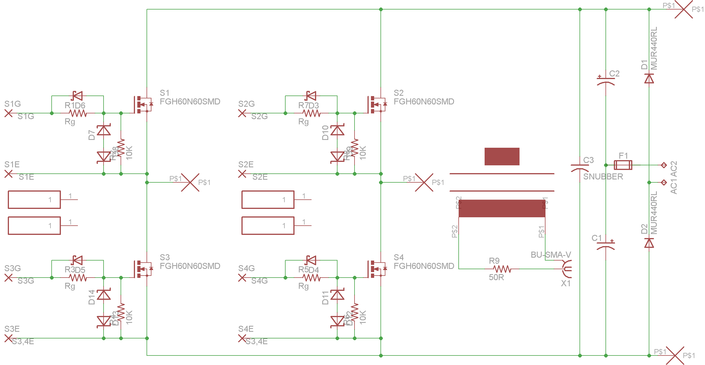
Eagle Schematic
You’ll note that I didn’t include a spot for TVS (transient voltage suppressors). You can deadbug them onto the IGBT pads, but given the laminated bus and the position of the snubber capacitor, I’m not sure it’s necessary. I haven’t had any problems with excessive buss ringing, even while hard-switching in my attempts to build a QCW:
Sort of…
Here’s a picture of the actual board once it’s populated. This was done using a temperature-controlled iron and some regular solder, no fancy surface mount equipment or supplies required. If the IGBT leads are left uncut, they make nice scope probe test points:

The snubber looks sad because it had a few angry encounters with a soldering iron when I was installing the IGBTs!
I will try to get some pictures of the bare boards soon. This was a test run from PCBFabExpress, which made 5 of these with a 2-day lead time and 2-day shipping for a net cost of something like $20 per board. Quite good! A future sendout would probably be done using MyroPCB, which makes higher-quality boards in a variety of colors. Their black boards have looked nice in the past (look up oneTesla and RageBridge to see what they might look like).
If you’re interested in participating in a group sendout, let me know! Comments, PMs, emails, etc. are all welcome. If there’s interest, I’ll write a assembly guide with some more documentation. In the meantime, I’ll post a parts list soon.
And here’s a shot of what an earlier prototype of this board did with when I put it in my DRSSTC (something like 250 – 300A peak primary current):

3’+ from a full bridge of TO247s.

Hello,
I tried to download the eagle file, but I don’t see the board or schematic and am interested in making this once at my local MakerSpace. Would you mind sending the files to me?
Thanks,
Joe
Hi Joe!
Looks like I forgot to put the eagle files into the zip download in addition to the gerber files. I’ve updated the zip file and if you try downloading it again, you should see a board and schematic file in there too.
Nice catch, and good luck,
Daniel
Hi,
I cannot download the Eagle Files.
Can you help me, please 😦 !
Thank you 🙂
Hi Adam,
I just tried clicking the Dropbox link and the download worked for me. Are you sure there aren’t filters wherever you are using the internet that are preventing you from downloading using the link?
Daniel
Yes, you’re right;
There is a filter in the network where I tested. I will try in my home, and I think, it will work.
Thank you 🙂
Hi,
You have checked any issues (coupling) with the gate drive traces and components and the high current secondary trace on top of the transistor package?
Thanks.
Yes, the gate waveforms look fine during normal DRSSTC operation.
Hi, would this inverter work to take in 110 V DC and outputting a 100 kHz + – 10kHz square wave?
Yes.