So it’s that time of the year again when classes end and I can take a break and write a blog post again!
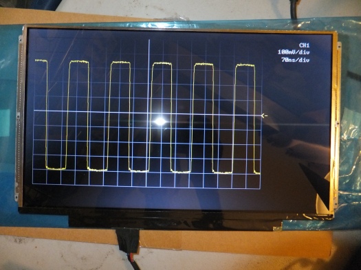
This semester I took 6.111: “Introductory Digital Systems Laboratory”, aka MIT’s FPGA lab, and produced a functional 2-channel 100MSPS, 25MHz analog bandwidth digital oscilloscope for my final project:
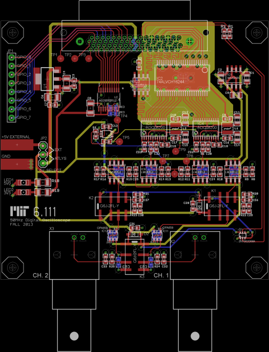
Half the project was designing and debugging a 4-layer analog front end and sampling board, and the other half was writing the Verilog code to make the thing work. The board layout looks like this (layer is 2 a continuous ground plane that is hidden):
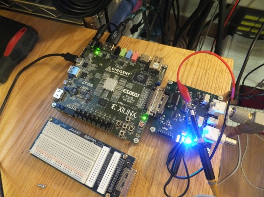
The FPGA I used was a Spartan 6 on a Digilent Atlys dev board. The Atlys was chosen due to its HDMI output capability and high speed 68-pin VHDCI connector that was used to interface with the custom front end board. The HDMI output was used to drive an OEM 13.3″ replacement laptop screen I found on eBay and hooked up to an HDMI to 40-pin LVDS controller:
The front end board contains a pair of TI ADC08200 ADCs that are clocked from the FPGA through a clock buffer IC. My code currently runs them at 100MSPS, but they’re rated for operation up to 200MSPS (potentially doubling the bandwidth of the scope to 50MHz). The ADCs’ reference voltage is set by an AD7801 parallel DAC, which, in addition to a switchable input attenuator, allows for different vertical scales. A few high speed opamps per channel buffer, scale, and offset the input signal (taken from a real scope probe!) into the somewhat narrow input range of the ADCs. Here’s: the schematic. My first trace was acquired with the analog processing bypassed and a signal generator feeding the ADC input directly:
Sadly enough, I forgot to decouple the opamps to ground (they were only decoupled from V+ to V-). When I first powered the analog processing section, the opamps oscillated and I measured 80mV of input offset voltage in one of the preamplifier stages, which was causing the output the drop outside of the input range of the ADCs. Adding decoupling capacitors from V+ to ground and V- to ground fixed the offset voltage problem and reduced some of the oscillations (remember: the input from the scope probe is referenced to ground, not V+ or V-!). Based on some advice from a friend who knows about fast analog things, I added some input pulldown resistors to one of the opamp stages in each channel, which reduced the effect of parasitic capacitances that can couple the output back into the noninverting input and create oscillations, and I got a trace with input from an oscilloscope probe. Here’s what that looked like:
Here’s: my final report (warning: big file!) for those that may be interested. Note that this was written in one all-nighter, the night after the all-nighter in which I got the last bits of the project working in time for the checkoff, so reader beware.
I’ll be working on adding more features like simultaneous display of both channels, better interpolation and horizontal scaling, and cursors and measurements in time to present this project at Techfair, so stay tuned for more updates! If time permits, I might even try making a new front end board with 1GSPS ADCs and a variable gain amplifier instead of a switched relay attenuator. Texas Instruments was generous enough to overnight all the ICs I used in this project that they manufacture after I entered their Analog Design Contest, so I might as well continue to make nicer boards… 🙂


That is a very neat design. Good luck with your project!
What software did you use to draw the first couple of block diagrams in your final report? They look very clean.
Hi David,
I used EAGLE to draw those diagrams — it’s not at all what that software is meant for, but it’s super simple and good enough for this application. I would recommend Inkscape or some other actual vector graphics tool.
Daniel
Ah, darn. I was hoping you had found some diagramming software that’s actually half decent. I’ve been using Powerpoint to draw stuff for project documentation, but it’s a PITA to use.